
The process of a dyno test on a Liebherr engine
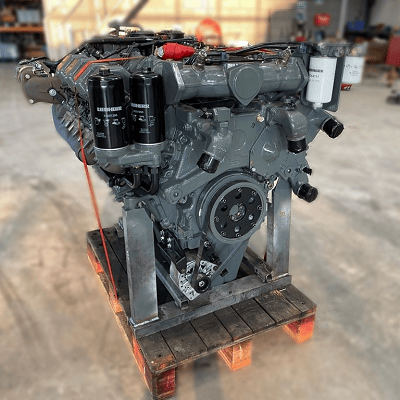
When it comes to heavy machinery, reliability and power are paramount. Liebherr, a name synonymous with innovation and excellence in engineering, stands tall as a pioneer in the realm of heavy equipment and machinery. From towering cranes to robust excavators, Liebherr’s engineering prowess extends to the heart of these machines. We delve into the world of dyno testing a Liebherr engine, uncovering the meticulous process behind unleashing the raw power concealed within.
The foundation of excellence
Before we embark on the journey of dyno testing, it’s crucial to understand the foundation upon which Liebherr engines are built. With decades of engineering expertise and commitment to quality, Liebherr engines are crafted to withstand the most demanding environment and deliver unparalleled performance. Each component is meticulously designed and rigorously tested to ensure reliability, efficiency and longevity.
The process
1 Preparation: The engine undergoes meticulous preparation before being mounted onto the dynamo meter. This includes ensuring all connections are secure, fluids are filled to the appropriate levels, and sensors are properly calibrated.
2 Mounting: The engine is carefully mounted onto the dynamometer, a specialized device designed to simulate real-world operating conditions. Precision is paramount during this step to ensure accurate results.
3 Initial checks: Once mounted, a series of initial checks are conducted to verify proper alignment, connection integrity, and functionality of all engine systems.
4 Warm-up: The engine is started and allowed to warm up to operating temperature. This ensures consistent results and minimizes the risk of damage during testing.
5 Baseline testing: With the engine warmed up , baseline tests are conducted to establish initial performance metrics. This includes measuring power output, torque, fuel consumption, and emissions at various RPM levels.
6 Load testing: The engine is subjected to progressively increasing loads to simulate different operating conditions, such as idle, partial load and full load. This allows engineers to assess performance across the entire operating range and identify any potential issues or optimization.
7 Data analysis: Throughout the testing process, data is continuously collected and analyzed in real-time. Advanced instrumentation and software are used to monitor performance metrics and identify trends or anomalies.
8 Optimazation: Based on the data analysis, adjustments may be made to optimize engine performance. This could involve fine-tuning fuel injection timing, adjusting air-fuel ratios, or optimize turbocharger boost pressure.
9 Validation: Once testing is complete, the results are meticulously reviewed and validated against predetermined criteria and specifications. Any deviations or anomalies are thoroughly investigated to ensure accuracy and reliability.
10 Reporting: Finally, a comprehensive report is generated detailing the results of the dyno testing, including performance metrics, observations, and any recommendations for further optimization or refinement.
The outcome of dyno testing
Dyno testing a Liebherr engine is more than just a routine procedure – it’s a testament to the unwavering commitment to excellence that defines Liebherr’s engineering philosophy. By subjecting their engines to rigorous testing and analysis, Liebherr ensures that each engine delivers the uncompromising performance, reliability, and efficiency that customers expect.
In conclusion, dyno testing a Liebherr engine is not just about measuring power output. It’s about unlocking the true potential of these remarkable engines and ensuring they exceed expectations in the most challenging environments imaginable.
The main products of hydraulic equipment are:
1. Hydraulic pump: mainly used to provide hydraulic oil power source.
2. Hydraulic cylinder: mainly used for the implementation of components, the hydraulic energy into mechanical energy.
3. Hydraulic motor: It is also the 1 kind of executive component, which converts hydraulic energy into rotary mechanical energy.
4. Hydraulic valve: used to control the pressure, flow and direction of the hydraulic system.
5. Hydraulic pipeline: used to connect various hydraulic components and transmit hydraulic oil.
6. Hydraulic oil tank: used to store hydraulic oil.
7. Hydraulic controller: used to control the operation of hydraulic equipment.
8. Hydraulic accessories: including various seals, connectors, pressure gauges, oil filters, etc.
9. Hydraulic press: such as hydraulic machine tools, hydraulic cranes, etc.
10. Hydraulic system: a system composed of the above various hydraulic equipment.
Hydraulic Parts,Hydraulic Components,Hydraulic Accessories,Hydraulic Fittings,Hydraulic Equipment Parts,Hydraulic Spare Parts
Huaian Yansheng Hydraulic Machinery Co., Ltd. , https://www.yshydraulics.com